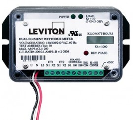
The Leviton 7B201-H01 dual element mini meter OEM module meets all measurement and verification based opportunities - including load management and LEED rating achievement. It's designed to provide a simple and effective process for accurately capturing measurements of power consumption, and is easy to specify and install for new construction and retrofits.
The Leviton 7B201-H01 dual element mini meter OEM module meets all measurement and verification based opportunities - including load management and LEED rating achievement. It's designed to provide a simple and effective process for accurately capturing measurements of power consumption, and is easy to specify and install for new construction and retrofits.
Discontinued!
This product has been discontinued and is no longer available.
There is no direct replacement, however we recommend the:
The replacement product is only available on our affiliate ITM.com website. Don't worry your cart and information will be brought over.
Not what you're looking for? Let’s do a search and help you find what you need.
Features
Applications
Use Mini Meters in multi-tenant residential and certain commercial industrial applications for:
| Electrical | |
| Input Configurations | 1 Phase, 2 Wire 1 or 2 Phase, 3 Wire |
| Supply Voltage Range (L1 or L2 to Neutral) | 102 VAC to 138 VAC |
| Maximum Input Power (L1 and L2) | 8 VA |
| Maximum Rated Current | 440 A primary for 400 A models 220 A primary for 200 A models 110 A primary for 100 A models 0.11 A secondary for 0.1 A secondary models 0.22 A secondary for 0.2 A secondary models |
| Line Frequency | 50 to 60 Hz |
| Power Factor Range | 0.5 to 1.0, Leading or Lagging |
| Accuracy | +/- 0.5% of registration @ 1.0pf. 2 to 200 A +/- 0.75% of registration @ 0.5pf, 2 to 200 A |
| Operating Temperature Range | -30 to 60°C |
| Rated Pollution Degree | 2 |
| Rated Relative Humidity | 80% |
| Inputs | |
| CT Inputs | CT1: X1 Current Transformer input, CT1. Colored wire of CT 1 CT1: X2 Current Transformer input, CT1. White wire of CT1 CT2: X1 Current Transformer input, CT2.Colored wire of CT2 (7B and 5B models only) CT2: X2 Current Transformer input, CT2. White wire of CT2 (7B and 5B models only) |
| Outputs | |
| 100, Isolated Output (100 Wh/P, Kh=100) | Isolated Pulse Output: 50 watthours on, 50 watthours off, referenced to ISOL COM |
| 1000, Isolated Output (1 kWh/P, Kh=1000) | Isolated pulse output: 500 watthours on, 500 watthours off, referenced to ISOL COM (not available on models with T suffix) |
| ISOL COM | Isolated common for 10/100/1000 isolated outputs |
| Counter (kh = 100 or kh = 1000) | For 12 VDC electro-mechanical counter |
| Counter (kh = 100 or kh = 1000) | For 12 VDC electro-mechanical counter |
| +12 VDC (MMS and MMD models only) | 12 VDC Output; current rating is 3 mA max. |
| LED Indicators | |
| Power LED (Green) | Illuminates when the meter is supplied with proper voltage |
| Load LED (Green) | 50% duty cycle (at constant load) LED to verify proper meter function when connected to a load. At 200 watts, LED will illuminate for 1.5 minutes, then turn off for 1.5 minutes; with no load, LED will remain on or off |
| Reverse Phase LED (Red) | Illuminates when a problem with meter phasing exists. With no load, LED may be on or off. See CT installation section for instructions. |
| LCD Display | Optional LCD display that shows total kWh |
Submetering How To Step 1 - Evaluate Facility
Submetering How To Step 2 - Energy Information Plan
Submetering How To Step 3 - Install